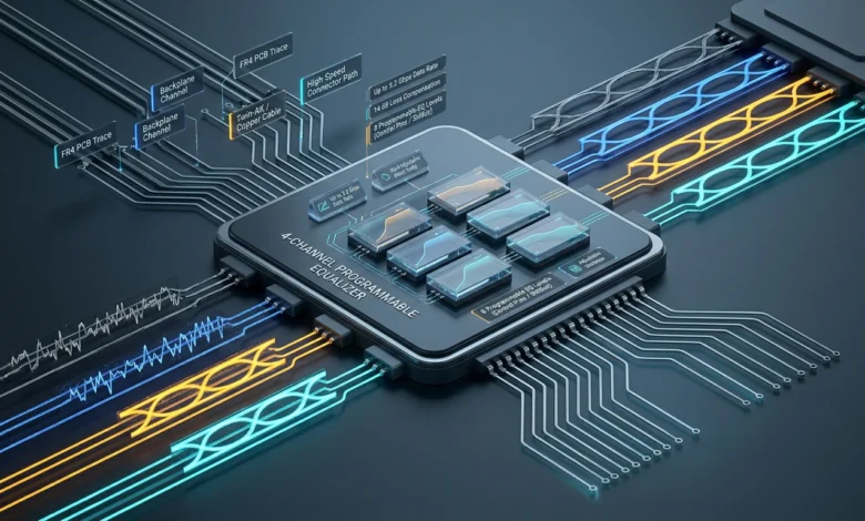
A quad equalizer is an electronic signal-conditioning device that applies equalization to four data channels within one integrated circuit or module. In high-speed digital systems, signals lose quality as they travel across printed circuit board traces, backplanes, or cables. An equalizer compensates for some of those transmission losses so the receiving circuit can recover the data more reliably.
The term is commonly associated with four-channel devices used in technologies such as DisplayPort, PCI Express, XAUI, InfiniBand, Ethernet, storage systems, and other high-speed serial links. Texas Instruments, Analog Devices, and Renesas have produced devices that fit this general description, although their speeds, protocols, control methods, and supported applications differ.
This guide explains what is, why signal equalization is necessary, how four-channel equalizers work, where they are used, and what engineers should compare when selecting one.
Table of Contents
What Is a Quad Equalizer?
A quad equalizer is essentially four equalization channels integrated into one device.
Each channel receives a high-speed signal that has been degraded as it travels through a transmission medium such as:
- an FR4 PCB trace;
- a backplane;
- a copper cable;
- a high-speed connector path.
The equalizer compensates for frequency-dependent signal loss before the signal reaches the next receiver or processing stage.
For example, Texas Instruments’ DS32EV400 is a four-channel programmable equalizer designed for data rates up to 3.2 Gbps. TI states that it can compensate for up to 14 dB of loss at 3.2 Gbps and provides eight programmable equalization levels for each channel.
Analog Devices’ MAX3980 is another example. It combines four equalizer lanes operating at 3.125 Gbps and was designed for XAUI applications.
The specific specifications vary, but the underlying purpose remains similar: improve signal quality across four high-speed data paths.
Also Read: Bodenxt What It Is and How Boden’s Green Transition Works
Why High-Speed Signals Need Equalization
Digital signals do not travel through real hardware without loss.
As signal frequencies increase, PCB traces, cables, connectors, and other interconnects can attenuate some frequency components more than others.
This creates distortion.
A clean digital transition sent by a transmitter can become increasingly rounded or difficult to distinguish by the time it reaches the receiver.
At sufficiently high speeds, neighboring bits can begin influencing each other. This is commonly associated with intersymbol interference, or ISI.
Analog Devices describes its MAX3980 as compensating for transmission-medium loss and reducing problems caused by noise and jitter across high-speed XAUI lanes.
Equalization attempts to compensate for this degradation.
It does not magically recreate information that has been completely lost. Instead, the circuit applies frequency-dependent compensation so the received waveform more closely resembles what the downstream receiver expects.
Why Is It Called a “Quad” Equalizer?
“Quad” simply refers to four channels.
Instead of using four completely separate equalizer ICs, manufacturers can integrate four lanes into one package.
This is particularly useful for interfaces that naturally operate across multiple high-speed lanes.
Texas Instruments’ DS32EV400, for example, contains four NRZ data channels. Each channel has independent signal detection and enable functions.
Renesas’ QLX4600-S30 similarly provides four receive-side equalizers intended for high-speed protocols including DisplayPort, PCI Express, InfiniBand, and 10GBase-CX4.
Integrating four lanes can reduce board space and simplify designs where multiple data paths need similar signal-conditioning functions.
How Does a Quad Equalizer Work?
A high-speed equalizer generally sits somewhere in the signal path between the transmitting and receiving components.
The simplified flow looks like this:
Transmitter → PCB trace or cable → Equalizer → Receiver
As the signal moves through the transmission medium, higher-frequency components may experience greater attenuation.
The equalizer applies compensation to counteract this frequency-dependent loss.
Different devices handle this in different ways.
Some use fixed or manually selectable equalization levels.
Others provide programmable settings.
Some can be configured using physical control pins, while more advanced devices may support a serial management interface.
For example, the DS32EV400 provides eight equalization settings that can be controlled through pins or individually through SMBus.
That flexibility lets an engineer adjust the amount of compensation according to the length and characteristics of the signal path.
What Is Programmable Equalization?
Not every PCB trace or cable introduces the same amount of loss.
A short trace may need relatively little compensation.
A longer trace may require considerably more.
Programmable equalization allows the designer to change the amount of compensation instead of using one fixed setting for every situation.
The TI DS32EV400 supports eight programmable levels. TI specifies operation over cables and FR4 traces and states that the device can operate at up to 3.2 Gbps over 40-inch FR4 traces under the conditions described for the product.
Renesas takes a similar adjustable approach with the QLX4600-S30. Its four equalizing filters can each be configured to one of 32 compensation levels.
More adjustment levels can provide greater flexibility, but the correct setting still depends on the actual channel characteristics.
Maximum equalization is not automatically the best setting.
Quad Equalizer vs Redriver
The terms equalizer and redriver are closely related, but they are not always identical.
An equalizer focuses on compensating for losses in the incoming signal.
A redriver can combine receive equalization with output-drive functions that help transmit a restored signal farther along the next section of the channel.
For example, Analog Devices describes the MAX14950 as a quad PCI Express equalizer/redriver. It combines programmable input equalization with output redrive circuitry and programmable output emphasis.
That makes it useful when the design needs both compensation for an incoming degraded signal and improved drive toward the next device.
When selecting a part, engineers should therefore determine whether they need:
receive equalization only;
equalization plus redrive;
output emphasis;
or a more complete signal-conditioning function.
Where Are Quad Equalizers Used?
The exact applications depend on the device generation and supported signal characteristics.
Common uses include high-speed computing, communications, storage, displays, networking, and test equipment.
DisplayPort
TI identifies DisplayPort as a primary application for the DS32EV400.
The device can compensate for losses across four high-speed channels, making the four-channel architecture relevant to multi-lane DisplayPort signal paths.
PCI Express
PCI Express is another important use case for multi-lane equalizers and redrivers.
Analog Devices’ MAX14950 is specifically designed as a quad PCI Express equalizer/redriver supporting Gen III, Gen II, and Gen I data rates.
In systems such as servers, industrial PCs, storage hardware, and communications equipment, long board traces or connectors can create signal-integrity challenges.
An equalizer or redriver can help compensate for those losses when correctly designed into the channel.
XAUI and Ethernet
XAUI uses multiple serial lanes and was designed for 10-Gigabit Ethernet-related interconnects.
Analog Devices’ MAX3980 contains four differential lanes operating at 3.125 Gbps and was designed around XAUI applications.
A cable-oriented related device, the MAX3981, provided four 3.125-Gbps equalizer channels for twin-axial cable links.
InfiniBand and High-Speed Interconnects
Some are designed to work across multiple protocol families.
Renesas lists DisplayPort, InfiniBand, PCI Express, and 10GBase-CX4 among applications for its QLX4600-S30 quad lane extender.
TI similarly lists DisplayPort, XAUI, InfiniBand, and other high-speed data applications for the DS32EV400.
This flexibility is possible because equalization fundamentally operates on signal characteristics, although protocol-specific requirements still matter when selecting a component.
What Is Deterministic Jitter?
Jitter describes variation in the timing of signal transitions.
At high data rates, excessive timing variation can make it harder for a receiver to determine where one bit ends and another begins.
Transmission-medium losses can contribute to deterministic jitter.
TI specifies a residual deterministic jitter figure for the DS32EV400 under defined operating conditions after equalization of a long FR4 trace.
Such figures are useful when comparing parts, but they should always be interpreted together with the conditions in the datasheet.
A number measured at one speed, trace length, loss profile, and test pattern should not automatically be assumed for a different system.
Where Should an Equalizer Be Placed?
Placement depends on the architecture and component.
Receive-side equalization is commonly positioned near the receiving end of a lossy channel so it can compensate for degradation accumulated across the trace or cable.
Some more advanced signal conditioners can be placed elsewhere in the path.
Analog Devices describes the MAX3987, for example, as an equalizer and preemphasis driver that can be used at the beginning, middle, or end of a channel.
PCB layout also matters.
At multi-gigabit speeds, impedance control, connector quality, routing geometry, return paths, vias, and trace matching can materially affect signal integrity.
An equalizer cannot compensate for every possible PCB design problem.
What Should You Compare When Choosing it?
The first specification to check is maximum supported data rate.
A component designed around 3.125 Gbps XAUI is not automatically appropriate for a much newer high-speed interface.
Next, compare:
Number of channels:
Confirm that four channels actually match the system architecture.
Maximum equalization:
Determine how much channel loss the device is designed to compensate.
Equalization control:
Check whether settings are fixed, pin-selectable, software-programmable, or adaptive.
Protocol compatibility:
Confirm that the electrical behavior matches the intended interface.
Supply voltage:
Make sure the required power rails are available.
Package:
Board space and routing around high-speed differential pairs can influence package selection.
Temperature range:
Industrial systems may require wider operating-temperature specifications.
Device lifecycle:
This is particularly important with older components.
For example, Analog Devices currently marks the MAX3980 as not recommended for new designs, while the MAX3981 is listed as obsolete.
By contrast, TI currently lists the DS32EV400 as active.
Lifecycle status should therefore be checked before designing an older part into a new product.
Is a Quad Equalizer an Audio Equalizer?
Not necessarily.
The word “equalizer” is also used in audio, where EQ controls frequency bands to change tonal balance.
However, the engineering results currently associated strongly with include four-channel high-speed signal-conditioning devices used for digital data transmission.
These devices do not function like the bass, midrange, and treble controls on an audio system.
Their purpose is signal integrity.
They compensate for channel loss so digital receivers can distinguish transmitted data more reliably.
FAQs
What is a quad equalizer?
It is an electronic signal-conditioning device containing four equalization channels. It is typically used to compensate for signal loss across high-speed cables, PCB traces, or backplanes.
Why does a quad equalizer have four channels?
The four-channel configuration is useful for interfaces and systems containing multiple parallel high-speed serial lanes.
What does an equalizer do to a digital signal?
It compensates for frequency-dependent attenuation introduced by the transmission channel, helping reduce distortion and improve signal integrity at the receiver.
Is every quad equalizer interchangeable?
No. Devices differ in supported data rate, protocol characteristics, equalization range, control method, supply voltage, package, and lifecycle status.
Conclusion
A quad equalizer provides four channels of signal equalization in one device, typically for high-speed digital interfaces where PCB traces, backplanes, cables, and connectors degrade signal quality.
The equalizer compensates for channel loss and can reduce distortion before the signal reaches its next receiver.
Products such as TI’s DS32EV400, Analog Devices’ MAX3980 and MAX14950, and Renesas’ QLX4600-S30 demonstrate how the same basic four-channel concept can be applied to different interfaces, speeds, and system requirements.
The correct component should be selected according to the actual channel loss, data rate, interface requirements, control method, PCB design, operating conditions, and current product lifecycle.
Most importantly, engineers should not treat as one specific product name. It describes a class of four-channel signal-conditioning devices, and the capabilities of individual parts can differ substantially.